- Home
-
Categories
- Car Diagnostic Tools
- Original Brand Tools
- Car Key Programmers
- OBD2 Code Scanners
- Truck Heavy Duty Scanners
- ECU Chip Tuning Tools
- Odometer Correction Tools
- VAG Diagnostic Tool
- Original Launch X431 Tools
- Original Autel Tool
- Original Xhorse Tool
- Key Cutting & Locksmith Tools
- Airbag/Service Reset Tools
- OBD2 Cables and Connectors
- AUGOCOM Camshaft Engine Timing Tool
- Other OBDII Vehicle Tools
- Car Key Blanks
- Car Key Chips
- Car Diagnostic Software
- Automotive Electrical Testers & Test Leads
- Auto HID Xenon Light and LED Light
- Automotive Electronics
- Repair & Maintenance Tools
- MB Star Diagnostic Tools
- Health Care
- Special Deals
- Consumer Electronics
- Home & Garden
- Outdoor
- Expired Tools
- Top Selling
- New Arrivals
- for MB
- for Porsche
- Xhorse
- for TOYOTA
- for FORD
- Order Tracking
- Drop-ship
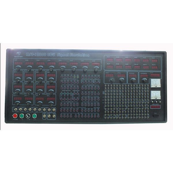
MST-12000 Universal Automotive Test Platform and ECU Signal Simulation
MST-12000 Universal Automotive Electrical and Electronic Bench
Item No. COBD24279 Price Down Notice
- Shipping:
- Airmail Post
Estimated delivery time: 7-45 working days.See details» - Returns:
- Return for refund within 7 days,buyer pays return shipping.Read details »
- Support:
-
 Online Chat
  WhatsApp
  Skype
Skype  Ask a question
- Product Details
- Product's Reviews
- Write a Review
- Related Products
MST-12000 Universal Automotive Test Platform and ECU Signal Simulation
Feature of MST-12000 Automotive Test Platform:
1. The all cars crankshaft signal simulation expert:
Twelve way set arbitrary waveform output, can produce all of today's car engine crankshaft, camshaft signal (Hall, magnetoelectric, photoelectric signal), waveform data will be pre-served by computer for long term.
2. All magnetoelectric crankshaft signal will be isolated by transformer, ensure no interference between signals.
3. The whole series of car sensor signal simulation expert:
The rotational speed signal, the speed signal (Hall, magnetoelectric, photoelectric signal), the ABS wheel speed signal, oxygen sensor signal, throttle valve, the accelerator
pedal signal, air flow meter, the intake pressure sensor (analog, digital), knock sensor etc signals simulation.
4. The All cars actuator drive experts:
Tachometer, odometer, blower control module, ignition module, frequency and pulse width control solenoid valve, car audio power amplifier.
5. The All cars actuator simulation expert
Diesel common rail injector, rail pressure control valve, ignition coil, injector, idle stepper motor, ultrasonic generator,etc actuator simulation.
MST-12000 Automotive Test Platform Fuctions:
The user can set crankshaft of different types according to different independent engine control system
1). The signal output (applicable to all car models of computer driven)
2). Automatic transmission input/output shaft signal simulation
3). Set to write into the waveform data directly
4). Engine revolving speed signal output
5). The speed signal output (hall signals, magnetoelectric)
6). Three or four channel ABS wheel speed signal output
7). Computer board working current test
8). EGR solenoid valve simulation
9). CANP Canister Purge solenoid simulation
10). Tachometer simulation and drive
11). Blower control module driver
12). Auxilliary air regulator simulation
13). Stepping motor simulation(Four/Six line)
14). Fuel injector simulation
15). Ignition coil simulation
16). The ignition module simulation
17). Reversing radar (ultrasonic) probe drive
18). The shift valve of automatic transmission simulation
19). Diesel injector simulation
20). Rail pressure regulator simulation
21). Shift quality valve simulation
22). Oil pressure regulating valve simulation
23). Water temperature, air temperature, outdoor temperature and evaporation temperature sensor signal simulation
24). Oxygen sensor signal simulation (manual)
25). The accelerator pedal double channel signal simulation
26). Throttle signal simulation
27). CANP Canister purge solenoid simulation
28). Air flow meter,manifold Absolute Pressure Sensor (analog, digital) signal simulation
29). Brake switch simulation
30). Clutch switch simulation
31). A\C request signal simulation
32). A\C relay simulation
33). Fule pump relay simulation
34). Radiator fan relay simulation
35). Audio signal output, power amplifier drive
36). Steering pressure switch simulation
37). Fuel injection pulse width measurement
38). Central door lock server simulation
39). Anti theft resistance simulation
40). Knock sensor signal simulation
41). Computer board working current test
42). User extensional functions
MST-12000 Instrument parameters:
1. Can set the waveform output: It can set twelve channels waveform output arbitrary, can simultaneously output crankshaft 1 º angle signal, the signal of cylinder detection,
TDC of cylinder 1 signal, camshaft signal, phase precision.This machine is applied to crankshaft and camshaft signal simulation of all vehicles worldwide; also applies
to the crankshaft and camshaft signal input, output simulation,and all of the automatic transmission input, output shaft signal simulation; ABS three or four channel wheel
speed signal simulation; computer set the waveform, and waveform can be long-term preservation;
2. Output signals: magnetoelectric signals, hall, photoelectric signal;
3. Duty cycle drive: duty cycle 1 ~ 99% continuous adjusting,frequency of 11 files regulation
4. The sensor signal simulation: resistance of 100 Ω ~10000 Ω voltage 0V~5V × 4 0V~1.5V
5. Actuator drive simulation: 69 channel output simultaneously
MST-12000 Instrument application:
1. Automobile sensor dynamic diagnosis, automobile engine, transmission, ABS, air conditioning, anti theft and other computer repair, auto teaching AIDS model driven, automobile production development;
2. The utility model is suitable for Germany, the United States, Japan, South Korea, and other domestic mini models etc hundreds of models;
Operation panel profile:
Output port: the above of the port said the abbreviation of the port name and the below is the port number (1-192) a total of 192 output ports.
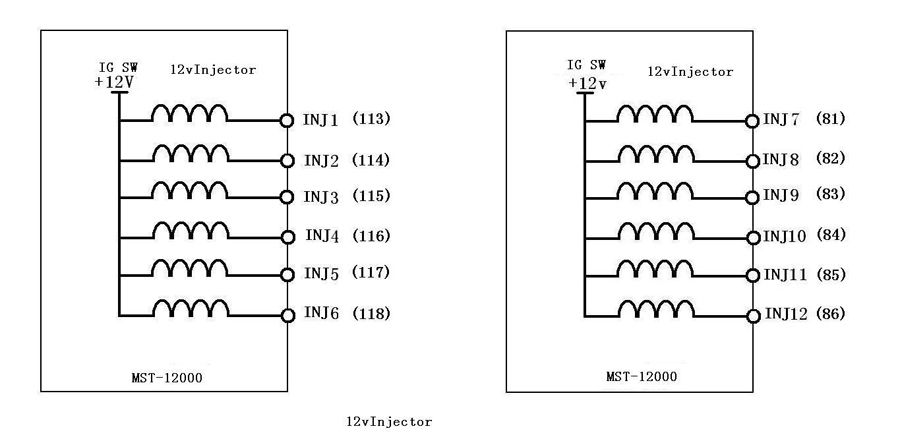
INJ1-INJ12 (port 81-86,113-118): making 1-12 cylinder injector and injection time (MS) (12V,gasoline)
SV1 (H) -SV6 (H) (port 129-134), SV1 (L) -SV6 (L) (port 145-150) diesel injector signal output (24V)
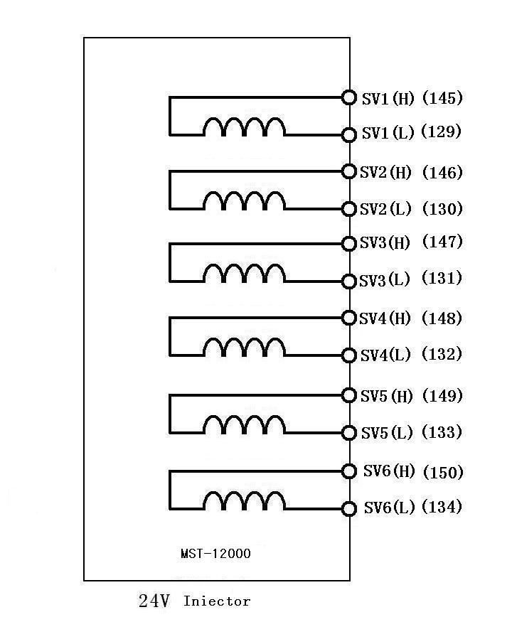
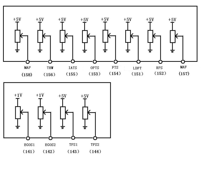
Analog output:
IATS: ( Port155 ) air charge temperature sensor 0-5V
THW:( Port156) water temperature sensor 0-5V
TPS1:( Port143) Throttle position sensor signal simulation 0-5V
TPS2: ( Port144) Throttle position sensor signal simulation ratio control 0-5V,used to adjust two throttle signal output ratio. If two throttle position sensor signals need to be 2:1, then adjust TPS1 output voltage to 1v, TPS2 0.5V. And then adjust the voltage of TPS1, two signals can be 2:1.
MAP:( Port158) Air intake pressure sensor signal simulation 0-5V
MAF:( Port57) Air flow meter signal simulation 0-5V
EGOS1:( Port141) Oxygen sensor signal simulation 0-1V
EGOS2:( Port 142) Oxygen sensor signal simulation 0-1V
LDFT:( Port151) Boost pressure sensor 0-5V
RPS; ( Port152) Fuel rail pressure sensor 0-5V
OPTS:( Port153) oil pressure sensor 0-5V
FTS: ( Port154) oil temperature sensor

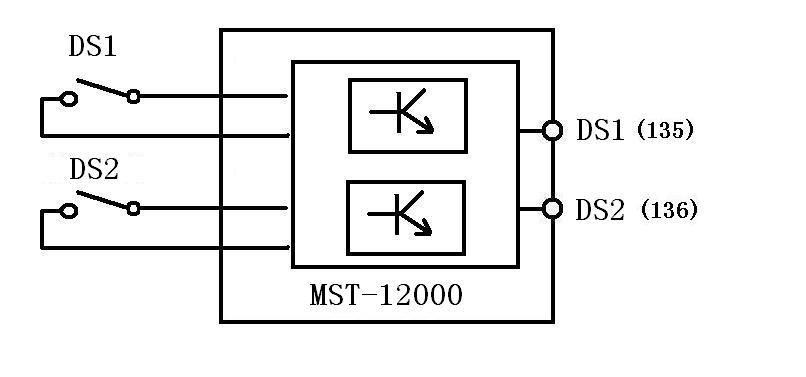
Digital signal output:
DS1:( Port135) knock sensor 1 signal simulation
DS2:( Port136) knock sensor 2signal simulation

CH0-CH7: ( Port41-48) The camshaft & crankshaft square wave signal
CH8-CH11: ( Port33-40) The camshaft & crankshaft ac signal( This feature requires a PC through good software calibration input signal of the crankshaft。 Click on a host "OUT" knob it can be output )
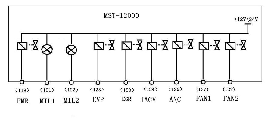
Components of simulation:
IACV: ( Port140 ) Idle speed control valve displacement simulation
PMR: ( Port135 ) pump relay fuel pump relay
EFI: ( Port136 ) main relay
MIL1: ( Port121) ] indicator light1
MIL2: ( Port122 ) indicator light 2
EGR: ( Port123 ) exhaust gas recirculation
EVP: ( Port125 ) CHARCOAL CANISTER-PURGE VALVE
A\C: ( Port126 )Air Conditioner Relay
FAN1: ( Port127) ELectric fan relay 1
FAN2: (Port128) ELectric fan relay 2

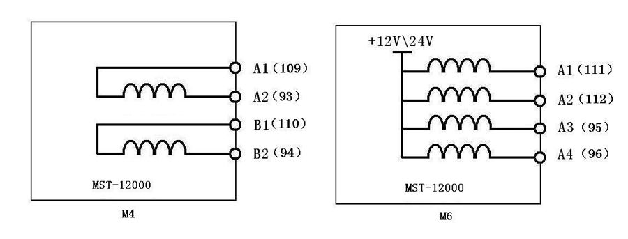
M4: ( M4Port Area, Port93、94、109、110 ) Four wire stepper motor simulation
M6: ( M6Port Area, Port95、96、111、112) Six line stepper motor simulation

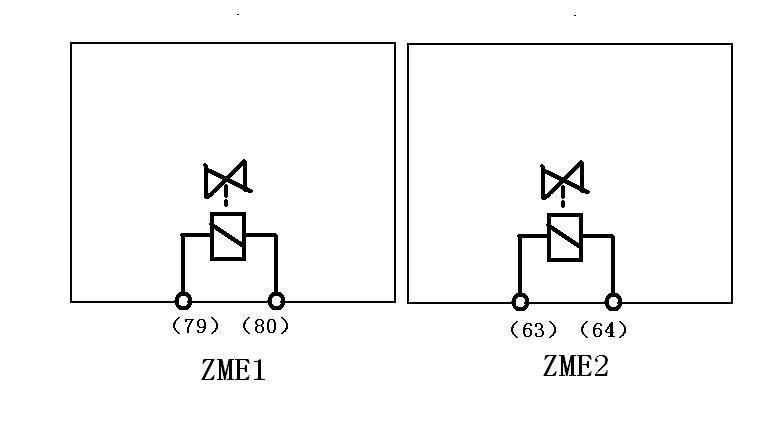
ZME1: ( Port79-80 ) Rail pressure regulator 1
ZME2: ( Port63-64 ) Rail pressure regulator 2 ( standby application )

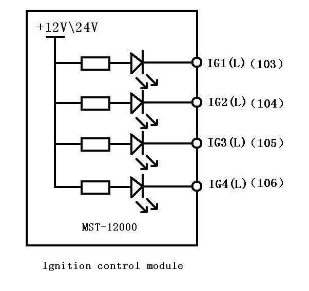
Ignition coil and ignition module simulation (B1-B6)
IG1 (L) -IG4 (L): (port 103-106) ignition coil and ignition module, indicator light negative
trigger

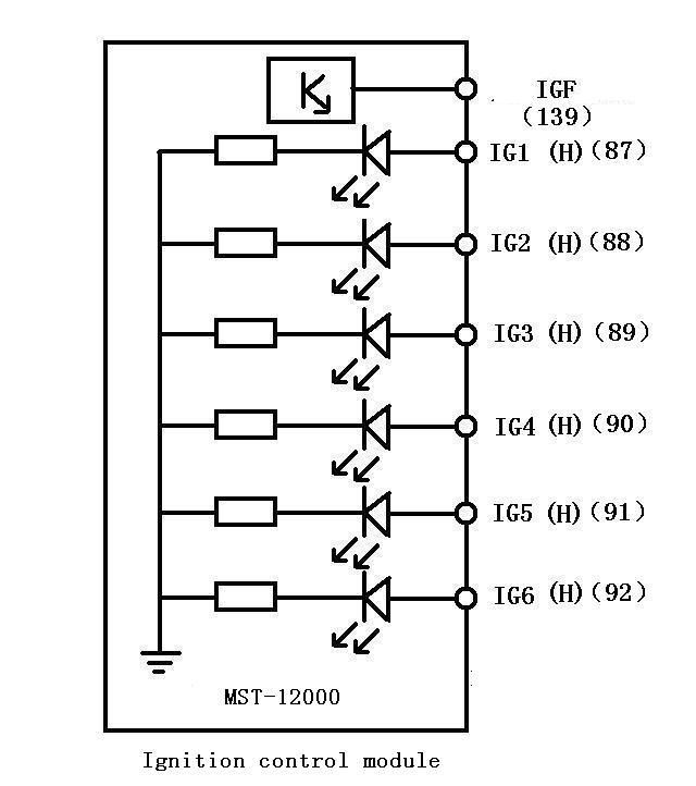
IG1 (H) -IG6 (H): (port 87-92) ignition coil and ignition module, the indicating lamp is triggered
IGF (port 139) ignition feedback signals
IGC1, IGC2: (port -107-108) ignition coil simulation:
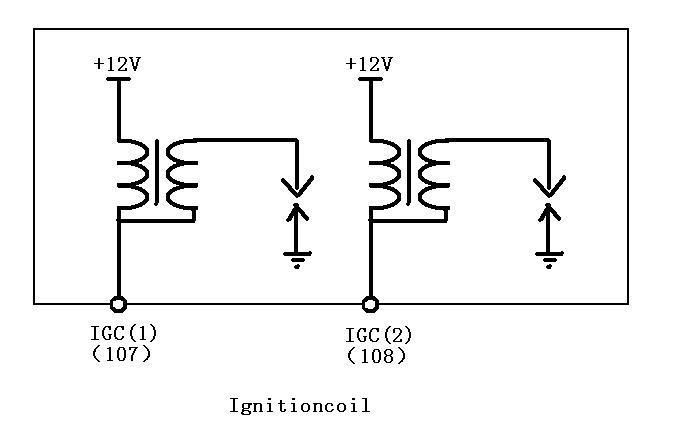

IGC1, IGC2: (port -107-108) ignition coil simulation:

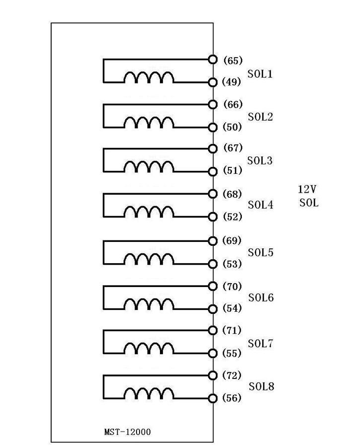
Electromagnetic valve simulation:
SOL1 - SOL8,49 (port 65-65-56)(12V)
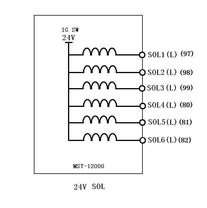
SOL1 (L) -SOL6 (L) (port 80-82,97-99) (24V)
SOL1-SOL6 (port 73-78,57-62)
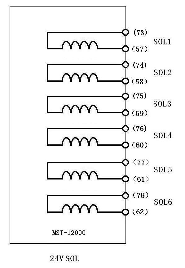


The power supply part:
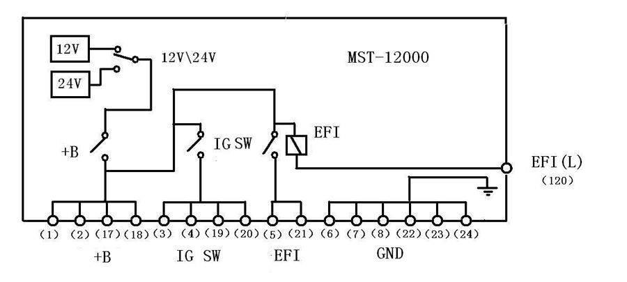
OBD diagnosis:
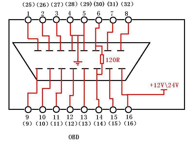
Digital Signals:
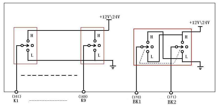
Triggered Relay:

OBD diagnosis:

Digital Signals:

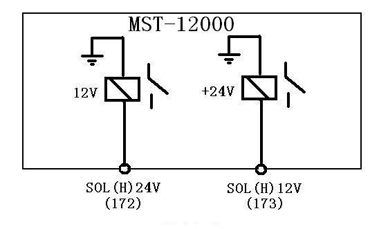
Triggered Relay:

Tachometer Signal:
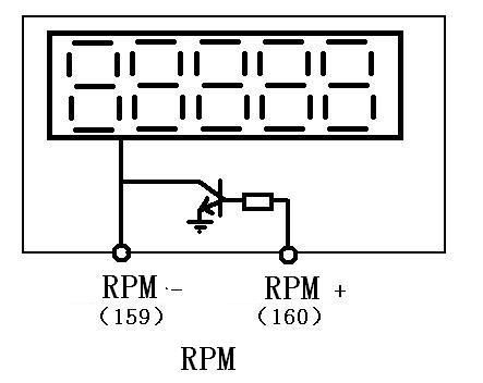

Wave setting software installation and use method:
Firstly, pls put the CD into the computer cd-rom,and open the software then copy the "simulation expert official version.Exe" file to the computer desktop and double-click the file,Double-click to open the desktop icon, the followings appear:
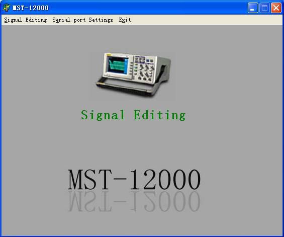
Click on the "signal editing", enter the signal editing interface.
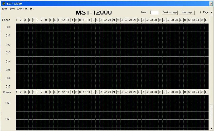
2. In thirty-sixth pulse position as the phase 72. In the "hase" input "72"
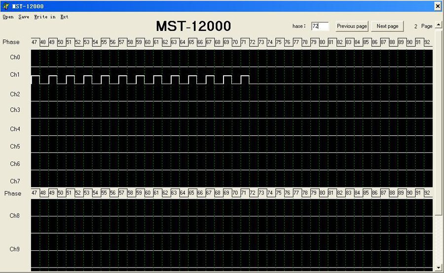
3. Between 36 pulse,remove two pulse at random and continuously, you can get 36-2 signal.
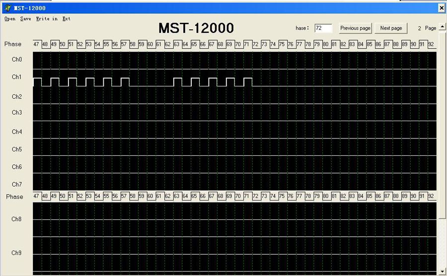
4. With the end phase number of 72\6=12, that means every 12 phase then click a pulse in CH0 ,can be set to the tachometer signal.

Click on the "signal editing", enter the signal editing interface.

Any set zone can be setted the waveforms you need arbitrary,CH0 is the tachometer channel, every 1 revolutions of the engine crankshaft, the channel 6 pulse.
CH1 -- CH7 is mainly used for square wave set, CH8-CH11 is mainly used for sine wave set. After the waveform set, input the waveform end position that we set the in the "hase" menu.
For example: editing a 36-2 square wave crankshaft signal in CH1, and repeat the cycle.
In the CH1 click 36 pulse continuous.
2. In thirty-sixth pulse position as the phase 72. In the "hase" input "72"

3. Between 36 pulse,remove two pulse at random and continuously, you can get 36-2 signal.

4. With the end phase number of 72\6=12, that means every 12 phase then click a pulse in CH0 ,can be set to the tachometer signal.
Packing list:
1set x The MST-12000 sensor signal simulator
60 pieces x The data line
1 piece x Power line
1 piece x The USB data line
1piece x Data disc



More
More
More
More
More
More
- Related Items
- Recommond Tools
- Hot Sale
- On Sale
- New Arrivals
- Freeshipping Items
-
US$159.00 / piece
-
US$639.00 / piece
-
US$55.00 / piece
-
US$179.00 / piece
-
US$699.00 / piece
-
US$82.00 / piece
-
US$1,299.00 / piece
-
US$749.53 / piece
-
US$629.00 / piece
-
US$69.99 / piece
-
US$859.00 / piece
-
US$249.00 / piece
-
US$55.00 / piece
-
US$69.99 / piece
-
US$627.00 / piece
-
US$929.00 / piece
-
US$117.00 / piece
-
US$274.28 / piece
-
US$2,374.05 / piece
-
US$599.00 / piece
-
US$39.90 / piece
-
US$274.28 / piece
-
US$47.63 / piece
-
US$209.00 / piece
-
US$599.00 / piece
-
US$589.00 / piece
-
US$299.00 / piece
-
US$19.99 / piece
-
US$148.00 / piece
-
US$34.00 / piece
-
US$47.21 / piece
-
US$95.00 / piece
-
US$178.00 / piece
-
US$26.99 / piece
-
US$1,227.00 / piece
-
US$699.00 / piece
Trending Products
- US$899.00 / piece
- US$229.00 / piece
- US$384.00 / piece
- US$199.00 / piece
- US$449.00 / piece
- US$550.05 / piece
 USD
USD Euro
Euro British Pound
 Australian Dollar




![[Full Version] V2022.12.1 KT200 ECU Programmer Master Version Support OBD BOOT BDM JTAG & ECU Maintenance/ DTC Code Removal With Free Damaos](/upload/pro/kt200-ecu-programmer-master-full-version-200.jpg)
