 USD
USD Euro
Euro British Pound
 Australian Dollar
- Home
-
Categories
- Car Diagnostic Tools
- Original Brand Tools
- Car Key Programmers
- OBD2 Code Scanners
- Truck Heavy Duty Scanners
- ECU Chip Tuning Tools
- Odometer Correction Tools
- VAG Diagnostic Tool
- Original Launch X431 Tools
- Original Autel Tool
- Original Xhorse Tool
- Key Cutting & Locksmith Tools
- Airbag/Service Reset Tools
- OBD2 Cables and Connectors
- AUGOCOM Camshaft Engine Timing Tool
- Other OBDII Vehicle Tools
- Car Key Blanks
- Car Key Chips
- Car Diagnostic Software
- Automotive Electrical Testers & Test Leads
- Auto HID Xenon Light and LED Light
- Automotive Electronics
- Repair & Maintenance Tools
- MB Star Diagnostic Tools
- Health Care
- Special Deals
- Consumer Electronics
- Home & Garden
- Outdoor
- Expired Tools
- Top Selling
- New Arrivals
- for MB
- for Porsche
- Xhorse
- for TOYOTA
- for FORD
- Order Tracking
- Drop-ship
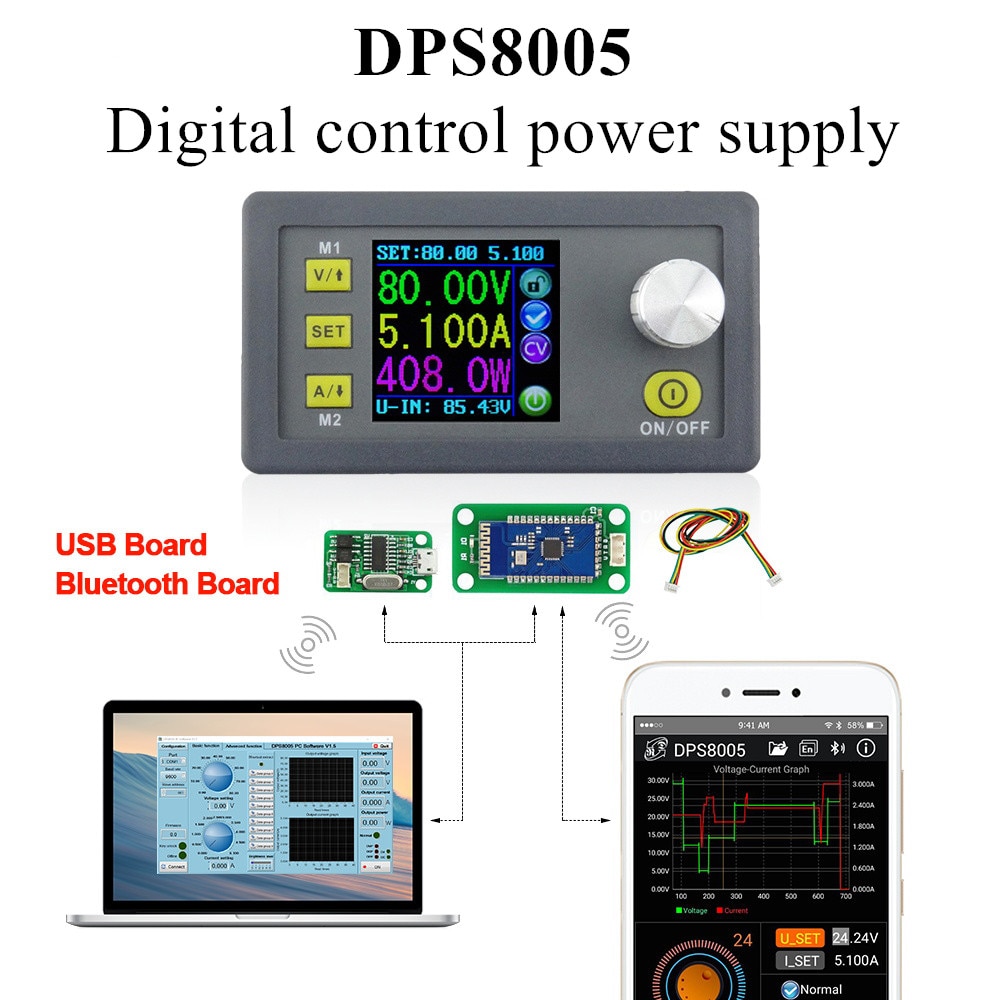

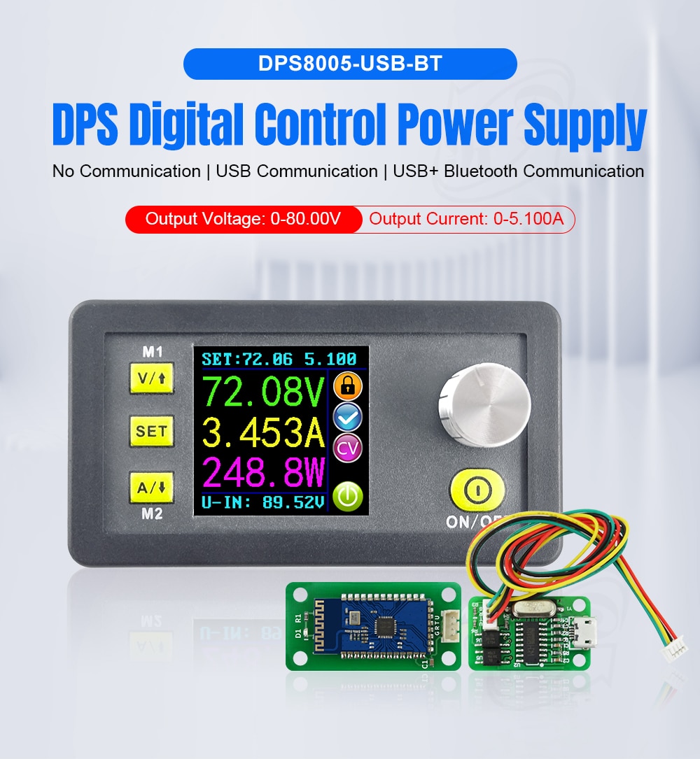
DPS8005 Digital control power supply constant voltage current Step-down power supply module Voltmeter Ammeter buck converter 80V
The fully adjustable output ranges from 0-80.00V in 0.01V (10mV) steps and the fully adjustable Current Limited output ranges from 0-5.100A in 0.001A (1mA) steps.
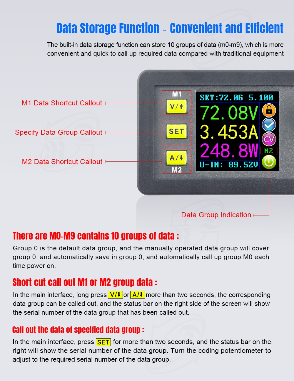
The unit offers non-volatile power off parameter storage and 10 programmable preset memory Data Groups with a quick recall function for groups 1 and 2.
- Price:
- US$49.00/ piece
- Discount Price:
- US$34.90/ piece 29%
- Color:


- Quantity:
-


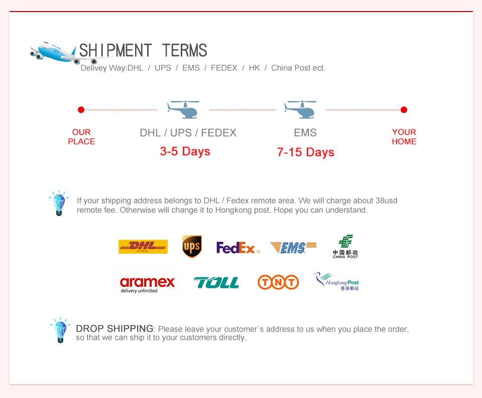
- Shipping:
- Airmail Post
Estimated delivery time: 7-45 working days.See details» - Returns:
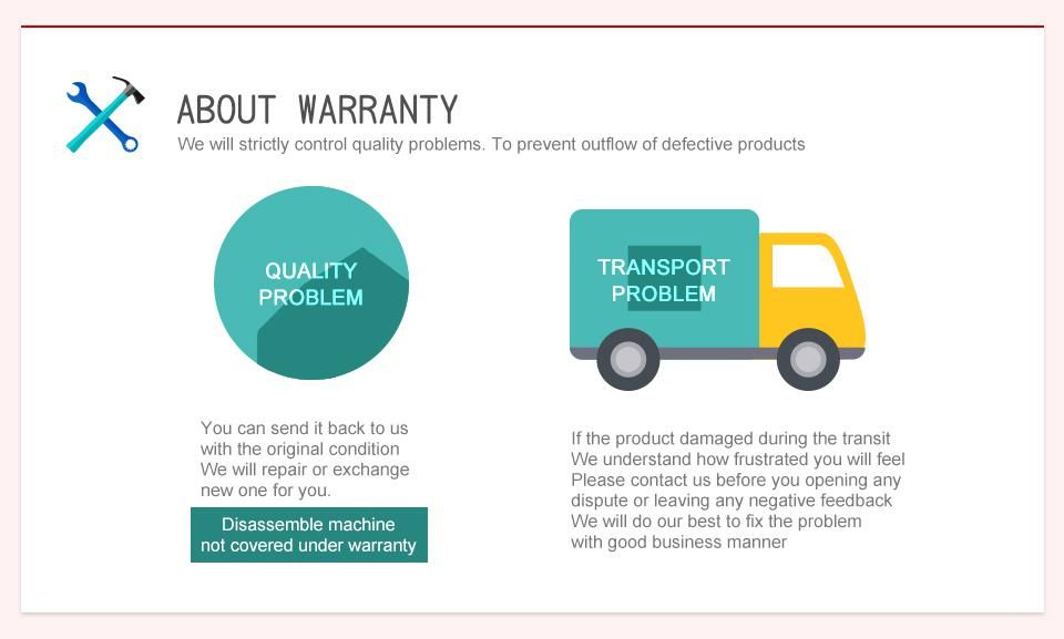
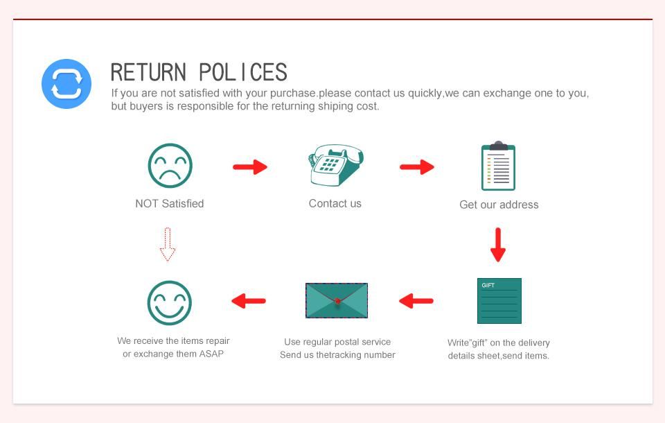
- Return for refund within 7 days,buyer pays return shipping.Read details »
- Support:
-
 Online Chat
  WhatsApp
  Skype
Skype  Ask a question


- Product Details
- Product's Reviews
- Write a Review
- Related Products
DPS8005 Digital control power supply constant voltage current Step-down power supply module Voltmeter Ammeter buck converter 80V 5A
General Information:
The programmable Power supply offers constant Current and constant Voltage and combines both analog and digital technology in an integrated and advanced design.
The fully adjustable output ranges from 0-80.00V in 0.01V (10mV) steps and the fully adjustable Current Limited output ranges from 0-5.100A in 0.001A (1mA) steps.
The unit offers non-volatile power off parameter storage and 10 programmable preset memory Data Groups with a quick recall function for groups 1 and 2.
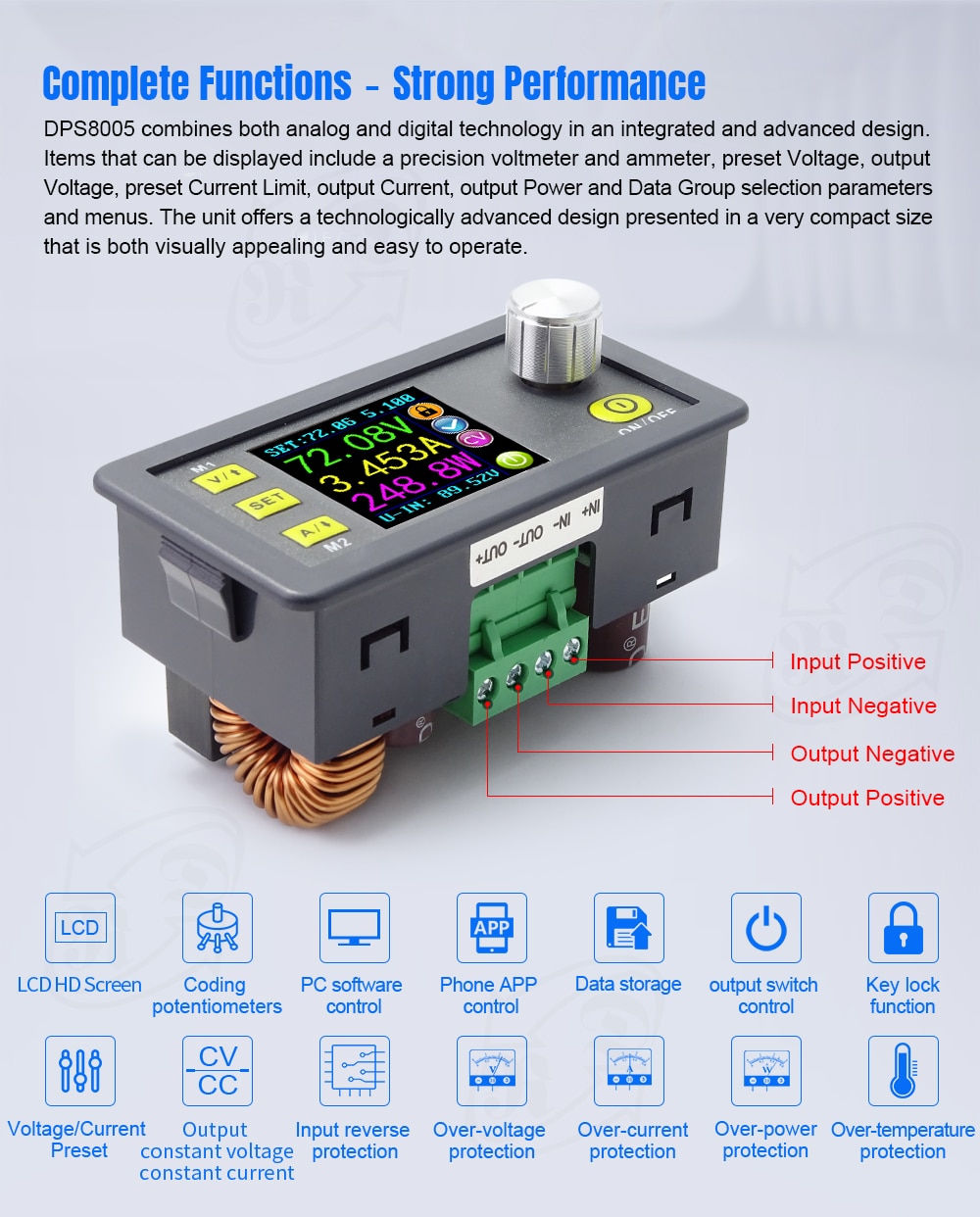
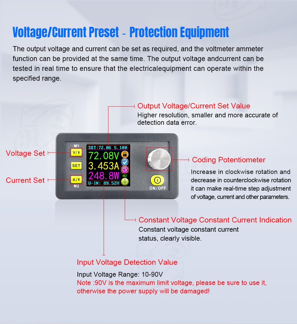
The digital control interface offers a comprehensive feature set not available on analog only power supplies. The keypad and rotary control offer simple input and selection of all required settings whilst the full colour LCD offers detailed display of the extensive but easily read information relating to system operation and performance. Items that can be displayed include a precision voltmeter and ammeter, preset Voltage, output Voltage, preset Current Limit, output Current, output Power and Data Group selection parameters and menus. Notification icons and text include indications such as output enabled or disabled, Constant Current or Constant Voltage mode of operation, abnormal condition warning, keypad locked or unlocked state and the Data Group in use. The Data Setting interface allows full adjustment of Over-Current, Over-Voltage and Over-Power protection values, Data Group settings and LCD brightness. The unit offers a technologically advanced design presented in a very compact size that is both visually appealing and easy to operate.
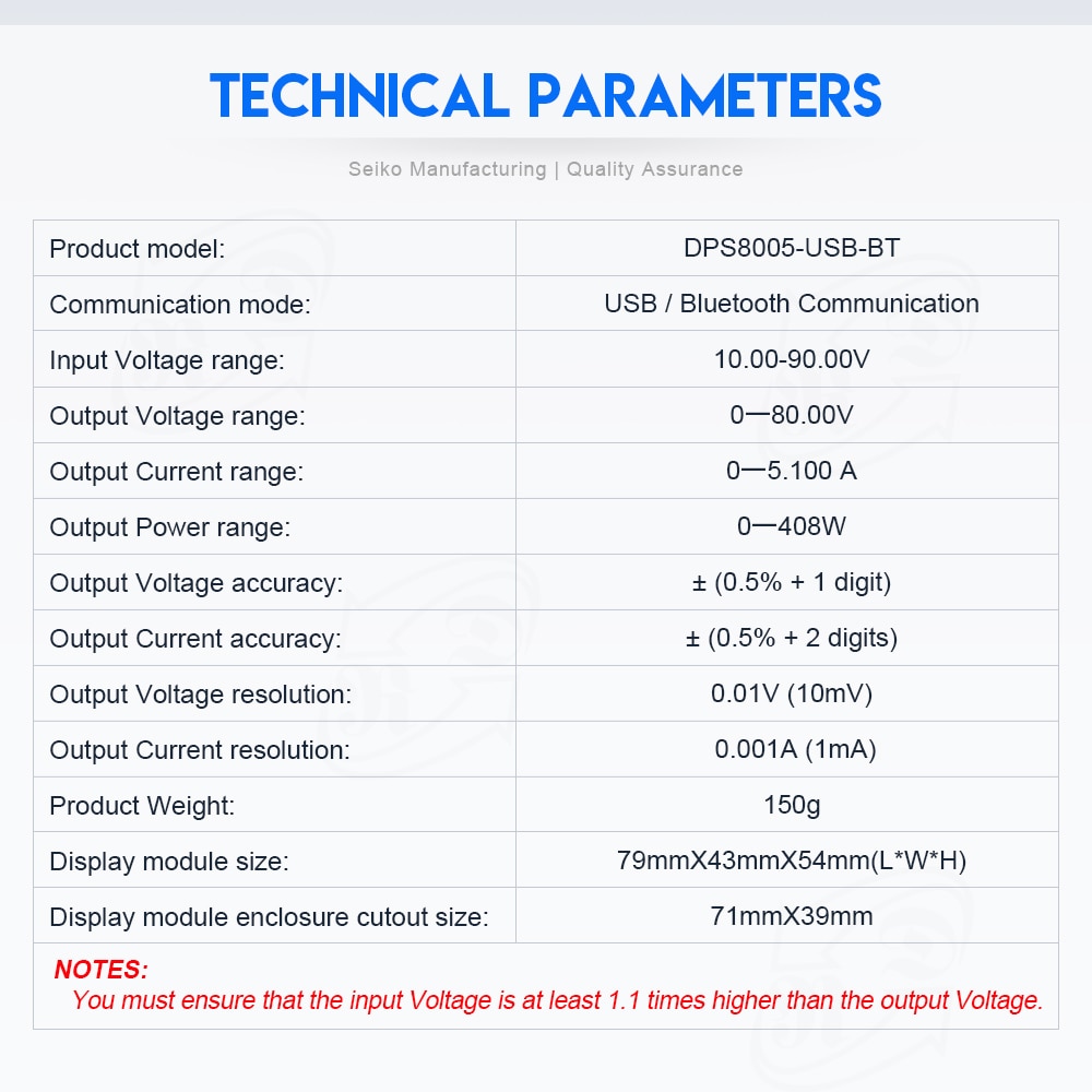
Technical parameters:
Input Voltage range: 10.00-90.00V
Output Voltage range: 0-80.00V
Output Current: 0-5.100A
Output Power range: 0-408W
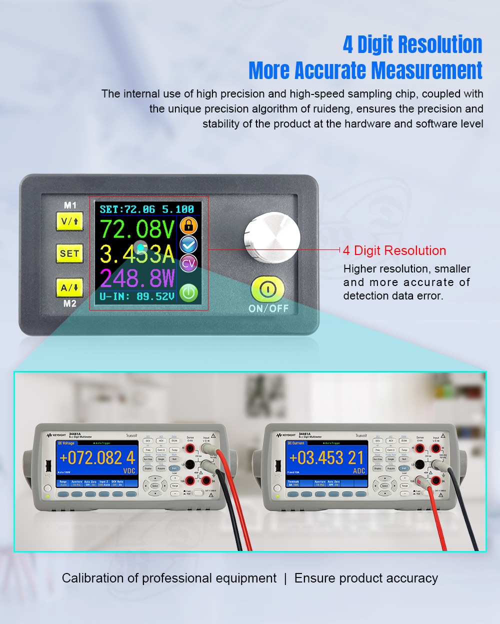
Output Voltage resolution: 0.01V (10mV)
Output Current resolution: 0.001A (1mA)
Output Voltage accuracy: ± (0.5% + 1 digit)
Output Current accuracy: ± (0.5% + 2 digits)
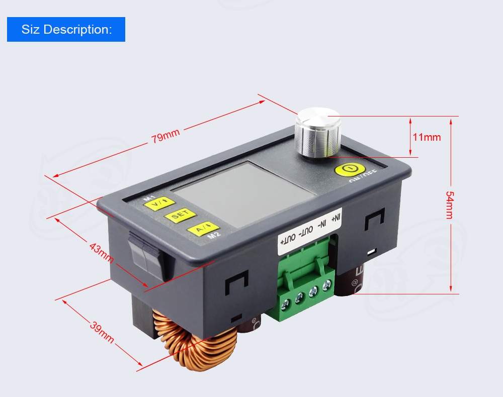
Product Weight: 150g
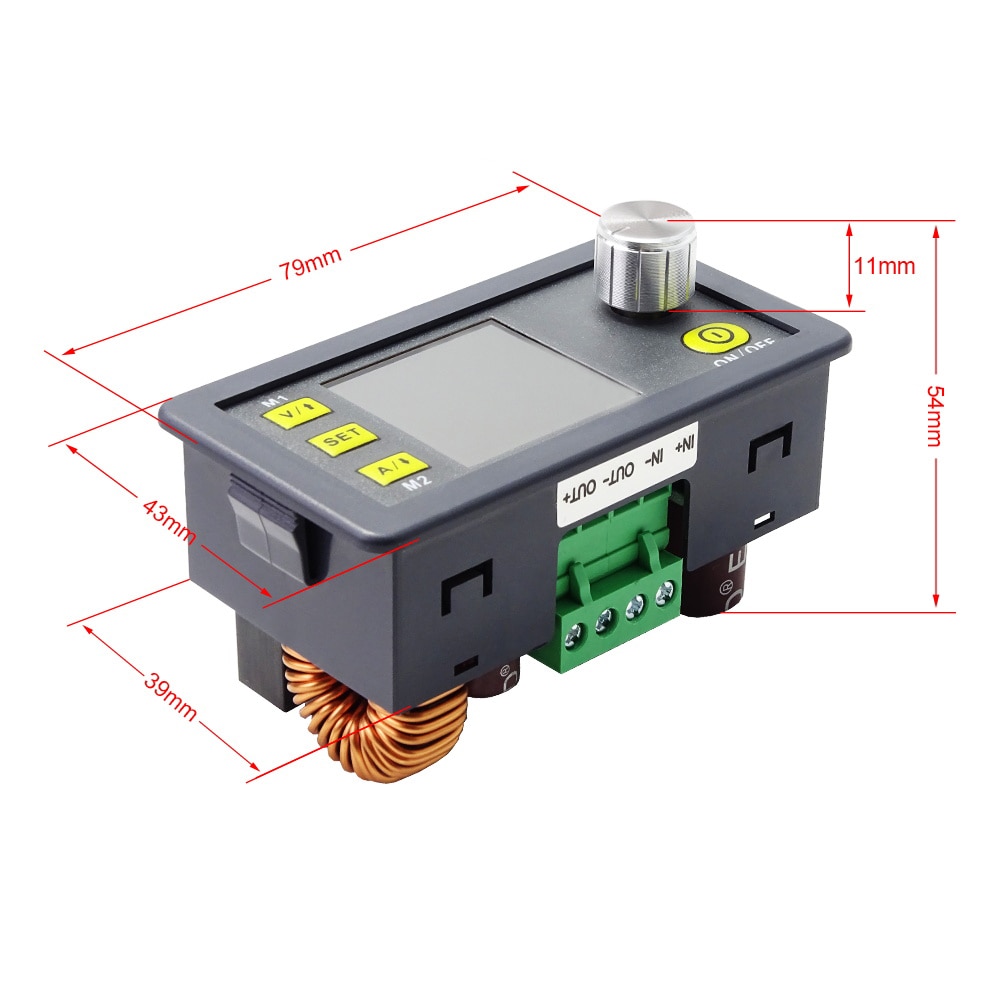
Display module size: 79*43*54(mm) (L*W*H)
Display module enclosure cutout size: 71mm*39mm
NOTES:
-
You must ensure that the input Voltage is at least 1.1 times higher than the output Voltage.
-
When the unit mounted in an enclosure it is absolutely vital to ensure appropriate ventilation for heat dissipation.
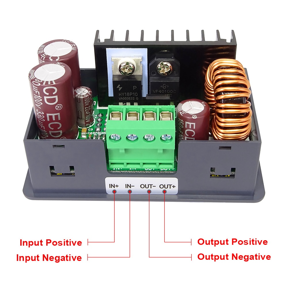
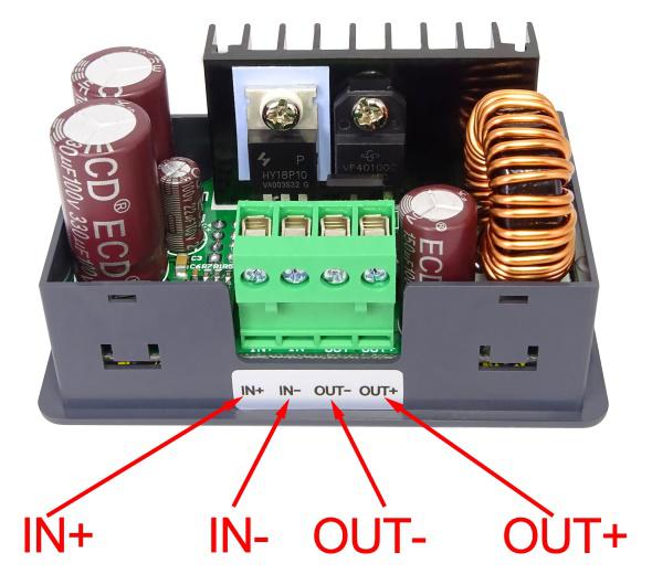
Connection details:
IN+ : Input positive IN - : Input negative
OUT+: Output positive OUT- :Output negative
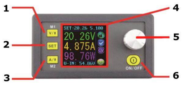
Panel description:
1. Voltage setting / Up Arrow / Shortcut to recall M1 Data Group.
2. Data entry / Extract data from the specified Data Group / Store value into the specified Data Group.
3. Current Limit setting / Down Arrow / Shortcut to recall M2 Data Group.
4. 1.44 inch full colour LCD screen.
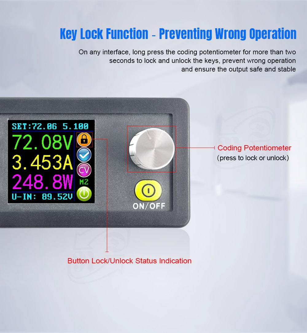
5. Rotary control / Data adjustment / Key lock.
6. Output On / Off.
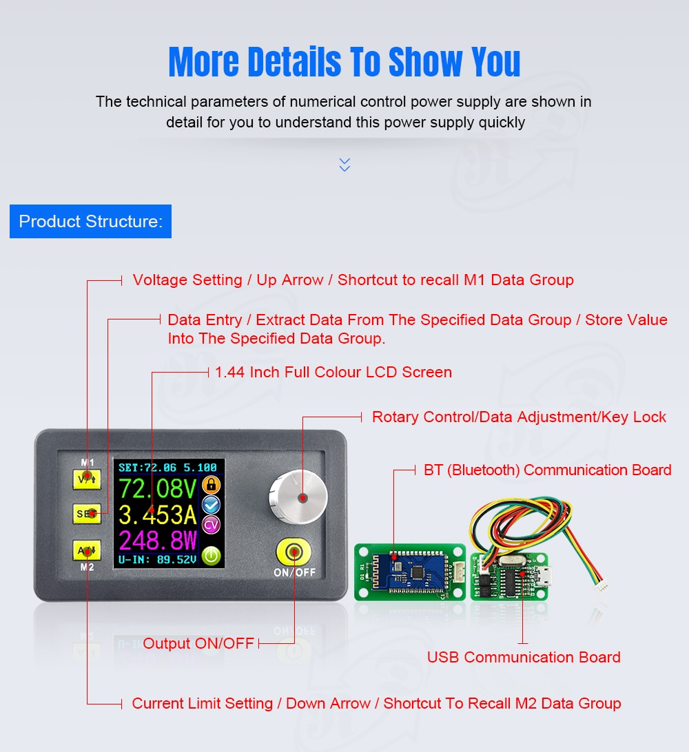


Display interface description
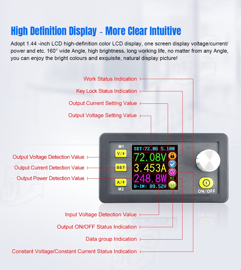
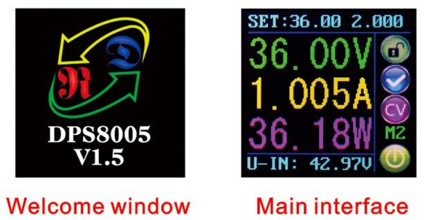
7. The preset value of the output Voltage.
8. The actual value of the output Voltage.
9. The actual value of the output Current.
10. The actual value of the output Power.
11. The actual value of the input Voltage.
12. The preset value of the output Current Limit.
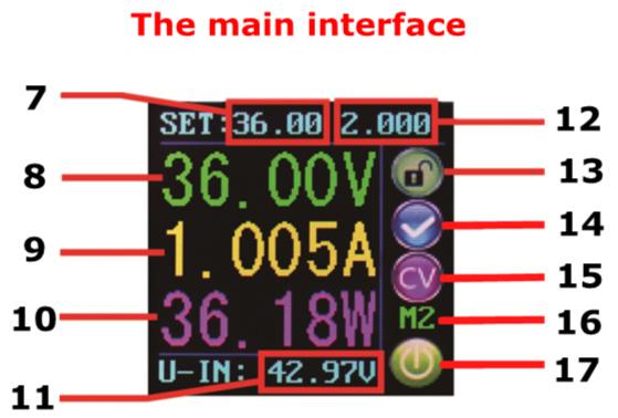
13. Keypad locked or unlocked prompt.
14. Normal or abnormal status prompt.
15. Constant Voltage or Constant Current status prompt.
16. Data Group number in use prompt.
17. Output enabled or disabled prompt
18. Preset output Voltage.
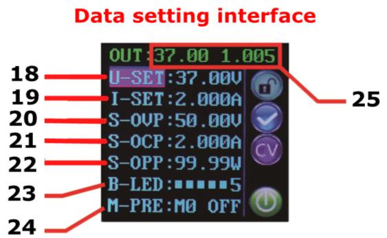
19. Preset output Current Limit.
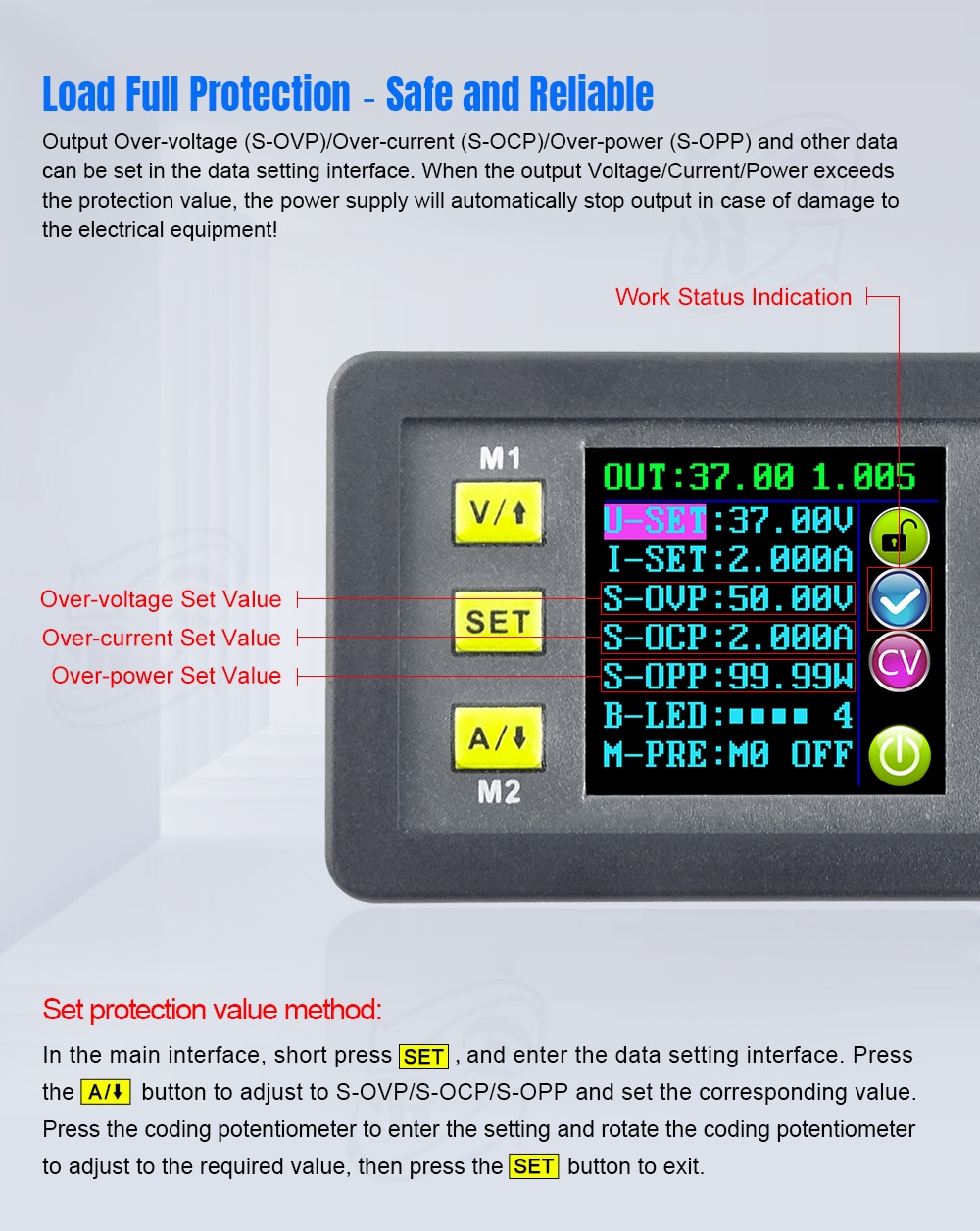
20. Preset Over-Voltage Limit.
21. Preset Over-Current Limit.
22. Preset Over-Power Limit.
23. Preset screen brightness level.
24. Preset Data Group number.
25. The actual value of the output Voltage and output Current.
Operating instructions
When the unit is first powered on the Welcome screen is displayed followed shortly by the Main Interface screen. On the Main Interface screen the selected (SET) Voltage and Current Limit values are displayed on the top of the screen. When the output is enabled the actual real output Voltage, Current and Power are displayed in the large font. The actual input Voltage is displayed at the bottom of the screen. On the right side of the screen are icons and prompts indicating system status. These are: keypad lock state icon, abnormal output status icon, Constant Voltage / Constant Current icon, preset Data Group memory number (when selected) and output enabled / disabled icon.
Set the output Voltage and output Current Limit via the Main Interface.
Press V/↑key to enter the Voltage setting mode. The Voltage setting numeric value will be highlighted by the cursor. Press the rotary control to place the cursor at the required character of the numerical value you wish to change. Further presses of the rotary control will cycle through the characters available. Turning the rotary control clockwise increases the value and anticlockwise decreases the value. Press V/↑again to exit. Alternatively, after 30 seconds of inactivity the setting mode will exit automatically. Press A/↓to set the output Current Limit using the same procedure.
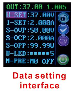
Set data values via the Data Setting Interface
Entering the Data Setting Interface
On the main interface press the SET key to enter the Data Setting Interface.
Set Voltage and Current Limit values
In the Data Setting Interface press V/↑or A/↓to step up or down through the menu options to select U-SET (Voltage) or I-SET (Current Limit), and then set the output Voltage and output Current Limit in the same way as used in the main interface. Press the SET key to return to the menu options and press the SET key again to exit.
Set the Protection Values.
Press V/↑or A/↓to step up or down through the menu options to select S-OVP (Over-Voltage Protection), S-OCP (Over-Current Protection) or S-OPP (Over-Power Protection) limits. Press the rotary control to place the cursor at the required character of the numerical value you wish to change. Set the value required in the same way as used in the main interface. Press the SET key to return to the menu options and press the SET key again to exit.
When any of the protection value limits are reached the output will be automatically disabled.
These are the global system protection limits and should not be confused with preset Voltage and Current.
Adjust the Screen Brightness
Press V/↑or A/↓to step up or down through the menu options to select B-LED, and then press the rotary control to highlight the brightness setting value. Turn the rotary control to adjust the brightness from 0 to 5 where 0 is the darkest and 5 is the brightest. Press the SET key to return to the menu options and press the SET key again to exit.
Data settings for each Data Group
Selecting the Data Group to edit
Press V/↑or A/↓to step up or down through the menu options to select M-PRE, and then press the rotary control. Turn the rotary control to select the number of the Data Group you wish to view and edit. After completing the desired setting press and hold the SET key until the Data Group number is shown on the right hand side of the screen. Pressing the set key again returns to the Data Group menu options.
Selecting M-Pre ON / OFF
Press V/↑or A/↓to step up or down through the menu options to select M-PRE, and then press the rotary control. Turn the rotary control to select the number of the Data Group you wish to view and edit then press the rotary control again to allow modification of the M-PRE option. Turn the rotary control to select either ON or OFF. When ON is selected it signifies that when the Data Group is recalled the state of the unit main output will remain the same as it was prior to the Data Group recall. When OFF is selected it signifies that when the Data Group is recalled the state of the unit main output will be set to OFF regardless of previous setting. Press and hold the SET key until the Data Group number is shown on the right hand side of the screen. The data value is now saved to the indicated Data Group number. Pressing the set key again returns to the Data Group menu options. To exit the Data Group menu press the set key again.
Adjust the selected DATA Group numerical values
To adjust any of the numerical values for the selected Data Group first use the V/↑or A/↓to step up or down through the menu options to select the item to change. Then press the rotary control and the numeric value will be highlighted by the cursor. Further presses of the rotary control will cycle through the characters available. Turning the rotary control clockwise increases the value and anticlockwise decreases the value. After setting the desired value press and hold the SET key until the Data Group number is shown on the right hand side of the screen. The data value is now saved to the indicated Data Group number. Pressing the set key again returns to the Data Group menu options. Repeat the above process for changing any of the other numerical values for the selected Data Group. To exit the Data Group menu press the set key again.
Selected Data Group output state at power on
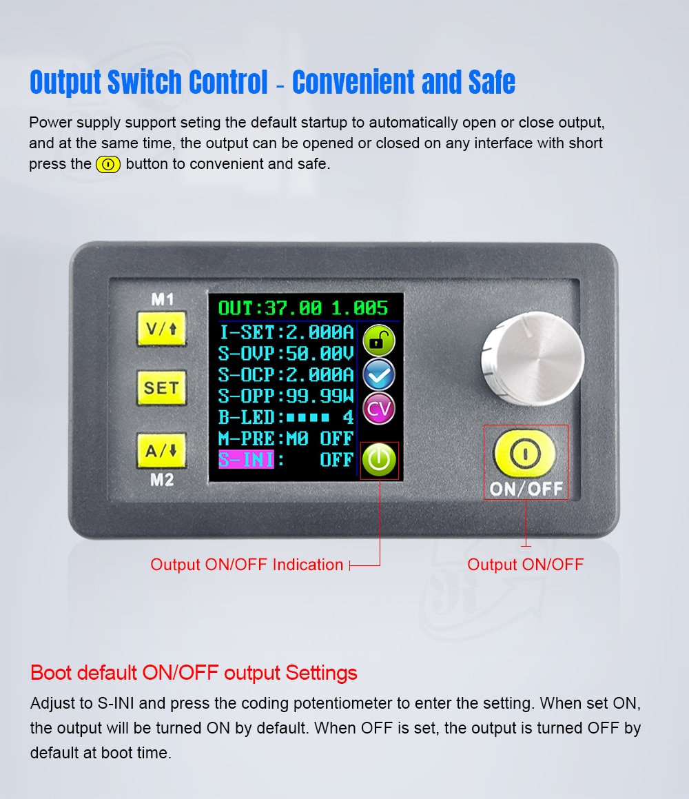
Press V/↑or A/↓to step up or down through the menu options to select S-INI and then press the rotary control to allow modification of the S-INI option. Turn the rotary control to select either ON or OFF. Selecting ON means the device will Power on with the Output enabled. Selecting OFF means the device will Power on with the Output disabled. After selecting the desired setting press and hold the SET key until the Data Group number is shown on the right hand side of the screen. The data value is now saved. Pressing the set key again returns to the Data Group menu options. To exit the Data Group menu press the set key again.
Other functions
Enable or Disable the Output.
At any time you can press the ON/OFF key to enable or disable the Output.
Locking the keypad to avoid accidental operation.
The keypad operation can be disabled to avoid accidental operation and unwanted changes. At any time you can simply press and hold the rotary control for more than 3 seconds to either lock or unlock all keys. The status of the key lock will be displayed at all times via the lock icon on the right side of the screen. Keypad locked is indicated by a closed padlock. Keypad unlocked is indicated by an open padlock.
M0-M9 Data Groups
M0 Data Group
The M0 Data Group is a special case. It is the power default Data Group. It should be noted that any time an alternative Data Group is selected or any changes made to the existing settings then M0 will be immediately overwritten with the newly selected data. In effect, M0 is always a real-time duplicate of the currently selected Data Group and data values. It is also the data-set that will be saved at power off and recalled at next power on. This happens automatically and transparently with no input necessary from the user.
Shortcut keys to select and recall M1 or M2 Data Group
From the main interface, press and hold V/↑or A/↓for more than 3 seconds to quickly recall the M1 or M2 Data Group. The corresponding Data Group number will displayed on the right of the screen. The M1 and M2 Data Groups are ideal choices for commonly used settings due to the quick recall function.
Select and recall any specific Data Group.
From the main interface, press and hold the SET key more than 3 seconds, M0 will be displayed on the right side of the screen. Turning the rotary control allows selection of the required Data Group (M1 to M9). To activate the selected Data Group press the SET key.
Display interface description
7. The preset value of the output Voltage.
8. The actual value of the output Voltage.
9. The actual value of the output Current.
10. The actual value of the output Power.
11. The actual value of the input Voltage.
12. The preset value of the output Current Limit.
13. Keypad locked or unlocked prompt.
14. Normal or abnormal status prompt.
15. Constant Voltage or Constant Current status prompt.
16. Data Group number in use prompt.
17. Output enabled or disabled prompt
18. Preset output Voltage.
19. Preset output Current Limit.
20. Preset Over-Voltage Limit.
21. Preset Over-Current Limit.
22. Preset Over-Power Limit.
23. Preset screen brightness level.
24. Preset Data Group number.
25. The actual value of the output Voltage and output Current.
Operating instructions
When the unit is first powered on the Welcome screen is displayed followed shortly by the Main Interface screen. On the Main Interface screen the selected (SET) Voltage and Current Limit values are displayed on the top of the screen. When the output is enabled the actual real output Voltage, Current and Power are displayed in the large font. The actual input Voltage is displayed at the bottom of the screen. On the right side of the screen are icons and prompts indicating system status. These are: keypad lock state icon, abnormal output status icon, Constant Voltage / Constant Current icon, preset Data Group memory number (when selected) and output enabled / disabled icon.
Set the output Voltage and output Current Limit via the Main Interface.
Press V/↑key to enter the Voltage setting mode. The Voltage setting numeric value will be highlighted by the cursor. Press the rotary control to place the cursor at the required character of the numerical value you wish to change. Further presses of the rotary control will cycle through the characters available. Turning the rotary control clockwise increases the value and anticlockwise decreases the value. Press V/↑again to exit. Alternatively, after 30 seconds of inactivity the setting mode will exit automatically. Press A/↓to set the output Current Limit using the same procedure.
Set data values via the Data Setting Interface
Entering the Data Setting Interface
On the main interface press the SET key to enter the Data Setting Interface.
Set Voltage and Current Limit values
In the Data Setting Interface press V/↑or A/↓to step up or down through the menu options to select U-SET (Voltage) or I-SET (Current Limit), and then set the output Voltage and output Current Limit in the same way as used in the main interface. Press the SET key to return to the menu options and press the SET key again to exit.
Set the Protection Values.
Press V/↑or A/↓to step up or down through the menu options to select S-OVP (Over-Voltage Protection), S-OCP (Over-Current Protection) or S-OPP (Over-Power Protection) limits. Press the rotary control to place the cursor at the required character of the numerical value you wish to change. Set the value required in the same way as used in the main interface. Press the SET key to return to the menu options and press the SET key again to exit.
When any of the protection value limits are reached the output will be automatically disabled.
These are the global system protection limits and should not be confused with preset Voltage and Current.
Adjust the Screen Brightness
Press V/↑or A/↓to step up or down through the menu options to select B-LED, and then press the rotary control to highlight the brightness setting value. Turn the rotary control to adjust the brightness from 0 to 5 where 0 is the darkest and 5 is the brightest. Press the SET key to return to the menu options and press the SET key again to exit.
Data settings for each Data Group
Selecting the Data Group to edit
Press V/↑or A/↓to step up or down through the menu options to select M-PRE, and then press the rotary control. Turn the rotary control to select the number of the Data Group you wish to view and edit. After completing the desired setting press and hold the SET key until the Data Group number is shown on the right hand side of the screen. Pressing the set key again returns to the Data Group menu options.
Selecting M-Pre ON / OFF
Press V/↑or A/↓to step up or down through the menu options to select M-PRE, and then press the rotary control. Turn the rotary control to select the number of the Data Group you wish to view and edit then press the rotary control again to allow modification of the M-PRE option. Turn the rotary control to select either ON or OFF. When ON is selected it signifies that when the Data Group is recalled the state of the unit main output will remain the same as it was prior to the Data Group recall. When OFF is selected it signifies that when the Data Group is recalled the state of the unit main output will be set to OFF regardless of previous setting. Press and hold the SET key until the Data Group number is shown on the right hand side of the screen. The data value is now saved to the indicated Data Group number. Pressing the set key again returns to the Data Group menu options. To exit the Data Group menu press the set key again.
Adjust the selected DATA Group numerical values
To adjust any of the numerical values for the selected Data Group first use the V/↑or A/↓to step up or down through the menu options to select the item to change. Then press the rotary control and the numeric value will be highlighted by the cursor. Further presses of the rotary control will cycle through the characters available. Turning the rotary control clockwise increases the value and anticlockwise decreases the value. After setting the desired value press and hold the SET key until the Data Group number is shown on the right hand side of the screen. The data value is now saved to the indicated Data Group number. Pressing the set key again returns to the Data Group menu options. Repeat the above process for changing any of the other numerical values for the selected Data Group. To exit the Data Group menu press the set key again.
Selected Data Group output state at power on
Press V/↑or A/↓to step up or down through the menu options to select S-INI and then press the rotary control to allow modification of the S-INI option. Turn the rotary control to select either ON or OFF. Selecting ON means the device will Power on with the Output enabled. Selecting OFF means the device will Power on with the Output disabled. After selecting the desired setting press and hold the SET key until the Data Group number is shown on the right hand side of the screen. The data value is now saved. Pressing the set key again returns to the Data Group menu options. To exit the Data Group menu press the set key again.
Other functions
Enable or Disable the Output.
At any time you can press the ON/OFF key to enable or disable the Output.
Locking the keypad to avoid accidental operation.
The keypad operation can be disabled to avoid accidental operation and unwanted changes. At any time you can simply press and hold the rotary control for more than 3 seconds to either lock or unlock all keys. The status of the key lock will be displayed at all times via the lock icon on the right side of the screen. Keypad locked is indicated by a closed padlock. Keypad unlocked is indicated by an open padlock.
M0-M9 Data Groups
M0 Data Group
The M0 Data Group is a special case. It is the power default Data Group. It should be noted that any time an alternative Data Group is selected or any changes made to the existing settings then M0 will be immediately overwritten with the newly selected data. In effect, M0 is always a real-time duplicate of the currently selected Data Group and data values. It is also the data-set that will be saved at power off and recalled at next power on. This happens automatically and transparently with no input necessary from the user.
Shortcut keys to select and recall M1 or M2 Data Group
From the main interface, press and hold V/↑or A/↓for more than 3 seconds to quickly recall the M1 or M2 Data Group. The corresponding Data Group number will displayed on the right of the screen. The M1 and M2 Data Groups are ideal choices for commonly used settings due to the quick recall function.
Select and recall any specific Data Group.
From the main interface, press and hold the SET key more than 3 seconds, M0 will be displayed on the right side of the screen. Turning the rotary control allows selection of the required Data Group (M1 to M9). To activate the selected Data Group press the SET key.

- Related Items
- Recommond Tools
- Hot Sale
- On Sale
- New Arrivals
- Freeshipping Items
-
 US$169.00 / piece
 -
 US$379.05 / piece
 -
 US$12.99 / piece
 -
 US$64.99 / piece
 -
 US$79.90 / piece
 -
 US$259.00 / piece
-
 US$1,149.00 / piece
 -
US$259.00 / piece
-
 US$499.00 / piece
 -
 US$99.00 / piece
 -
 US$1,956.05 / piece
 -
 US$490.00 / piece
-
 US$69.99 / piece
 -
 US$899.00 / piece
 -
 US$229.00 / piece
 -
 US$119.00 / piece
 -
 US$389.00 / piece
 -
 US$489.00 / piece
-
 US$27.99 / piece
 -
 US$674.50 / piece
 -
 US$209.00 / piece
 -
 US$84.99 / piece
 -
 US$426.55 / piece
 -
 US$22.99 / piece
-
 US$4,299.00 / piece
 -
 US$249.00 / piece
 -
 US$649.00 / piece
 -
 US$99.65 / piece
 -
 US$157.00 / piece
 -
 US$1,069.00 / piece
-
 US$119.71 / piece
 -
 US$18.99 / piece
 -
 US$14.99 / piece
 -
 US$21.00 / piece
 -
 US$41.99 / piece
 -
 US$152.15 / piece
Trending Products
- US$12.99 / piece
 US$229.00 / piece
 US$159.00 / piece
- US$389.00 / piece
 US$89.00 / piece
 US$79.00 / piece