DY29 Auto Car Break Out Box
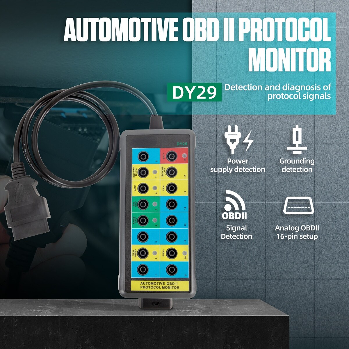
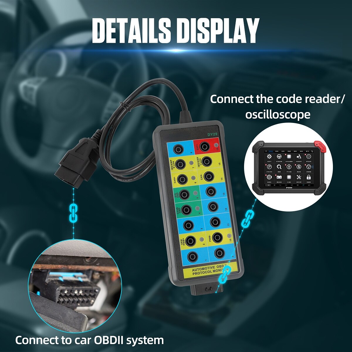
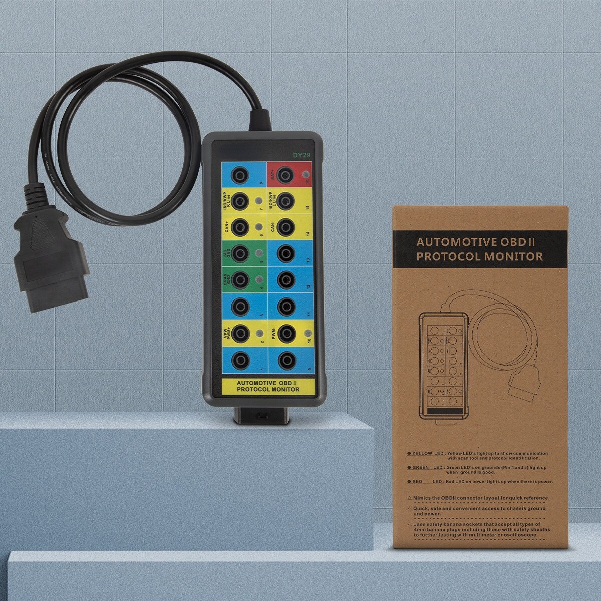
DY29 This is an automotive tool for the OBDII diagnostic link connector which offers easy access to the OBDII connector for monitoring signals of protocol,power and grounds conveniently and safely. It can be also connected to multi-meter or oscilloscope for further testing once unconfirmed signals detected.
DY29 Auto Car Break Out Box OBDII OBD Breakout Box Car Protocol Detector Car OBD2 Interface Car Monitor is a one of our DY29 Auto Car Break Out Box Tools, you can buy DY29 Auto Car Break Out Box OBDII OBD Breakout Box Car Protocol Detector Car OBD2 Interface Car Monitor from ukobd2.com.
Wholesale Top quality VAS6154, GM Tech2, VCM II For Ford, Handy Baby II Car Key Chip Copier, CDP DS150
images of DY29 Auto Car Break Out Box OBDII OBD Breakout Box Car Protocol Detector Car OBD2 Interface Car Monitor
DY29 New Auto car Break out Box OBDII obd Breakout Box Car Protocol Detector car obd2 interface car monitor
Product Description
DY29 This is an automotive tool for the OBDII diagnostic link connector which offers easy access to the OBDII connector for monitoring signals of protocol,power and grounds conveniently and safely. It can be also connected to multi-meter or oscilloscope for further testing once unconfirmed signals detected.

FEATURES
- Probing at the OBDII connector is no longer required.
- Easily access each of the 16 pins while scan tool communicating with vehicle.
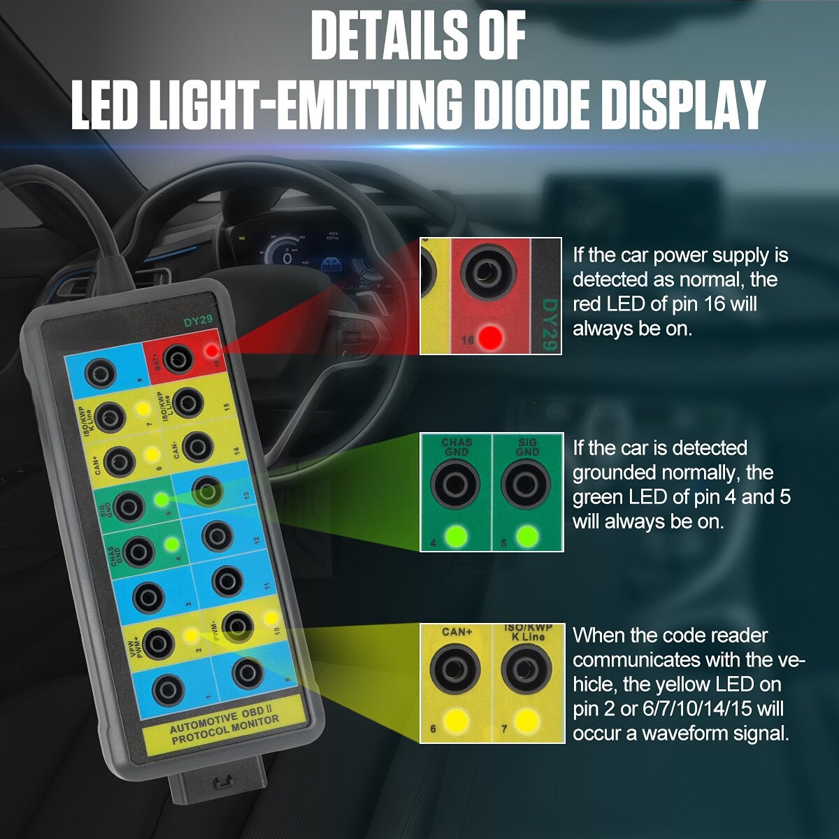
- LEDs to quickly indicate power or ground problems of OBDII connector.
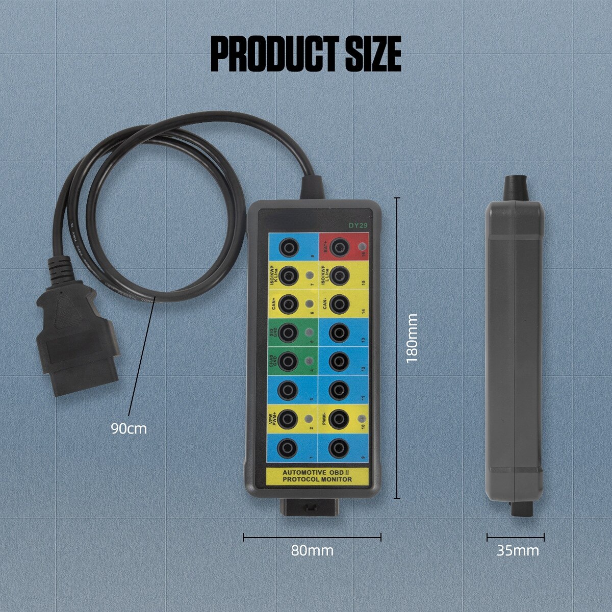
- Mimics the OBDII connector layout for quick reference.
- Quick, safe and convenient access to chassis ground and power by this monitor.
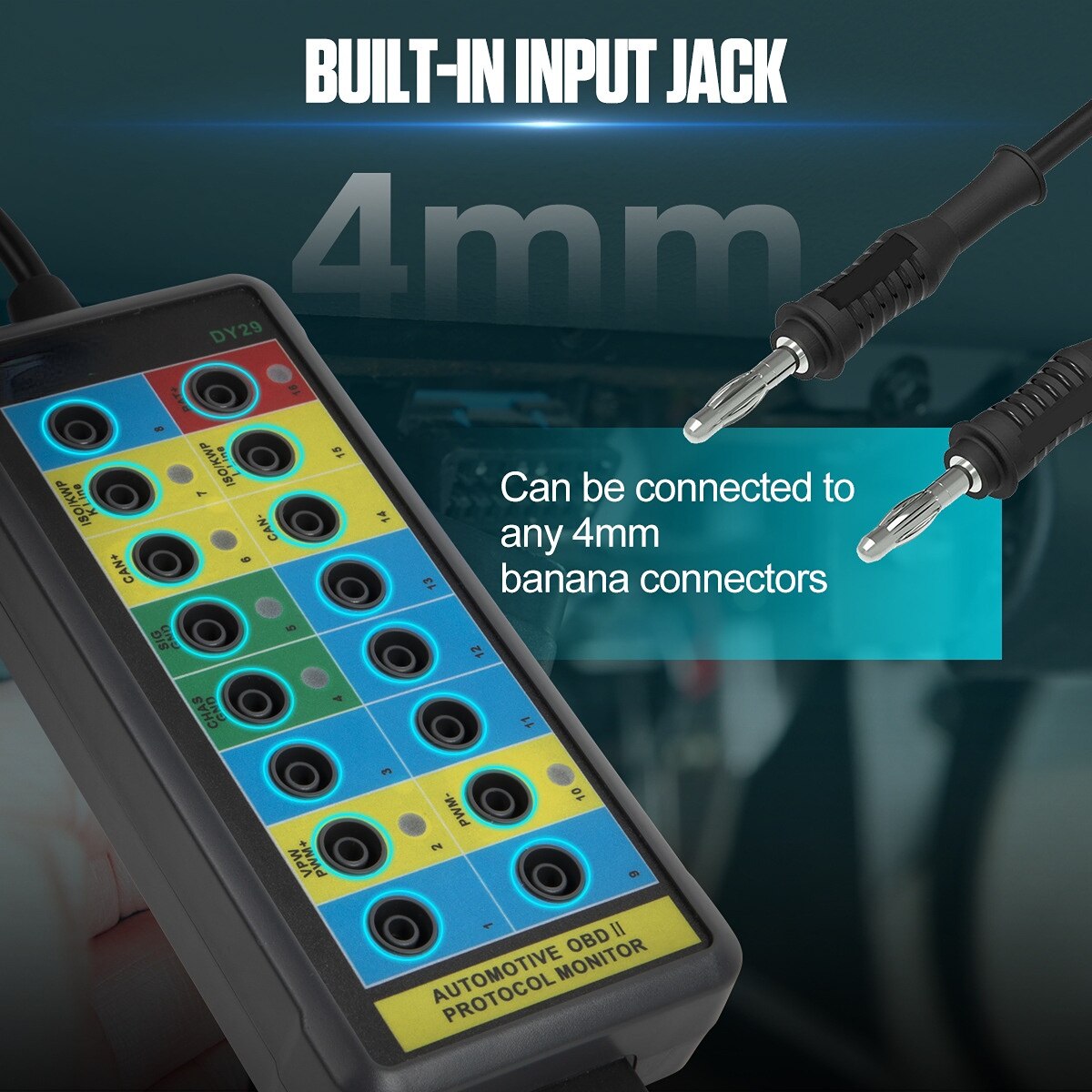
- Uses safety banana sockets that accept all types of 4mm banana plugs including those with safety sheaths.


LED INDICATIONS
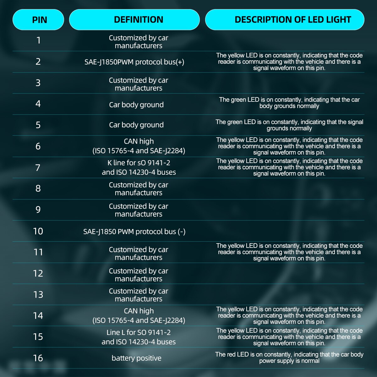
Yellow LED (Pin 2/6/7/10/14/15)
Light up to show communication with scan tool and protocol
identification.
Green LED (Pin 4/5)
Light up to show ground is good.
Red LED (Pin16)
Light up to show there is power.
CAUTIONS I DISCLAIMERS
-This tool is designed for use by automotive professionals.
-This tool provides easy access to the vehicle data bus lines.
-Improper use of this tool can result in damage to the vehicle data communication system and associated circuits and systems.
-Do not jumper pins together without understanding the circuits.
-Do not use the tool to power up a load device exceeding 1 amp.
-Do not place a jumper between the power pin 16 and ground pins4, 5.When this monitor is engaged the yellow L EDs will flash when changes take place on the corresponding data line. The flashing L EDs will allow you to determine the activity on that line. The green and red LEDs corresponding to OBDII connector pin4,5 and 16 are always active.
PACKING LIST
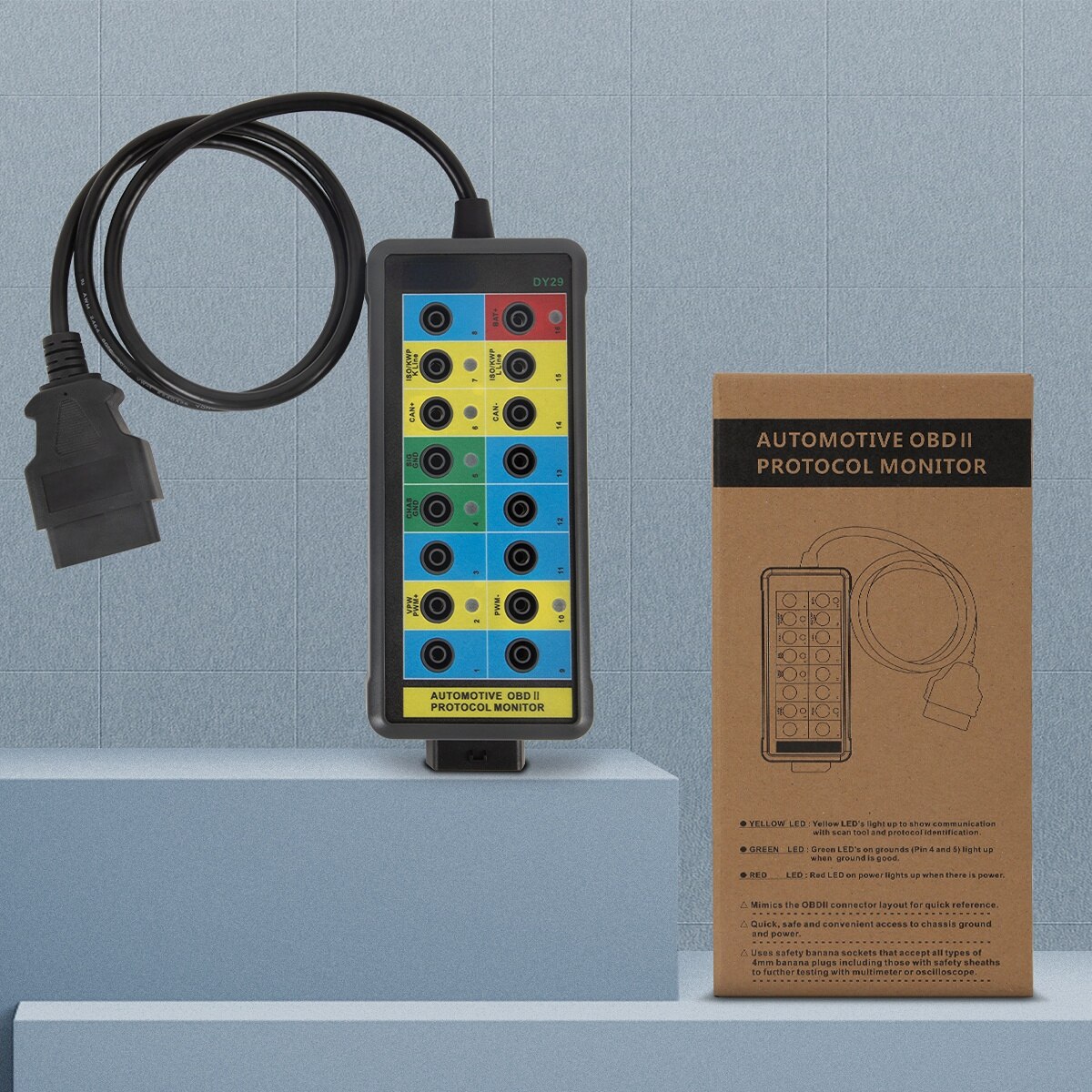
Manual*1
Host*1